Implementação da Estrutura da Internet das Coisas
Para a implementação da estrutura de uma rede IoT devemos construir um nó gateway, um controlador e nós finais (Sensores e Atuadores).
O rádio nRF24l01+ se comunica com Arduino via interface SPI. O rádio deve ser alimentado com uma tensão de 3.3 volts.
Como o radio possui conector de 8 pinos não é possível conecta-lo a protoboard. Então devemos utilizar conectores macho-fêmea, como ilustra a Figura 3, para fazer ligação ou construir um shield para adaptação do módulo.
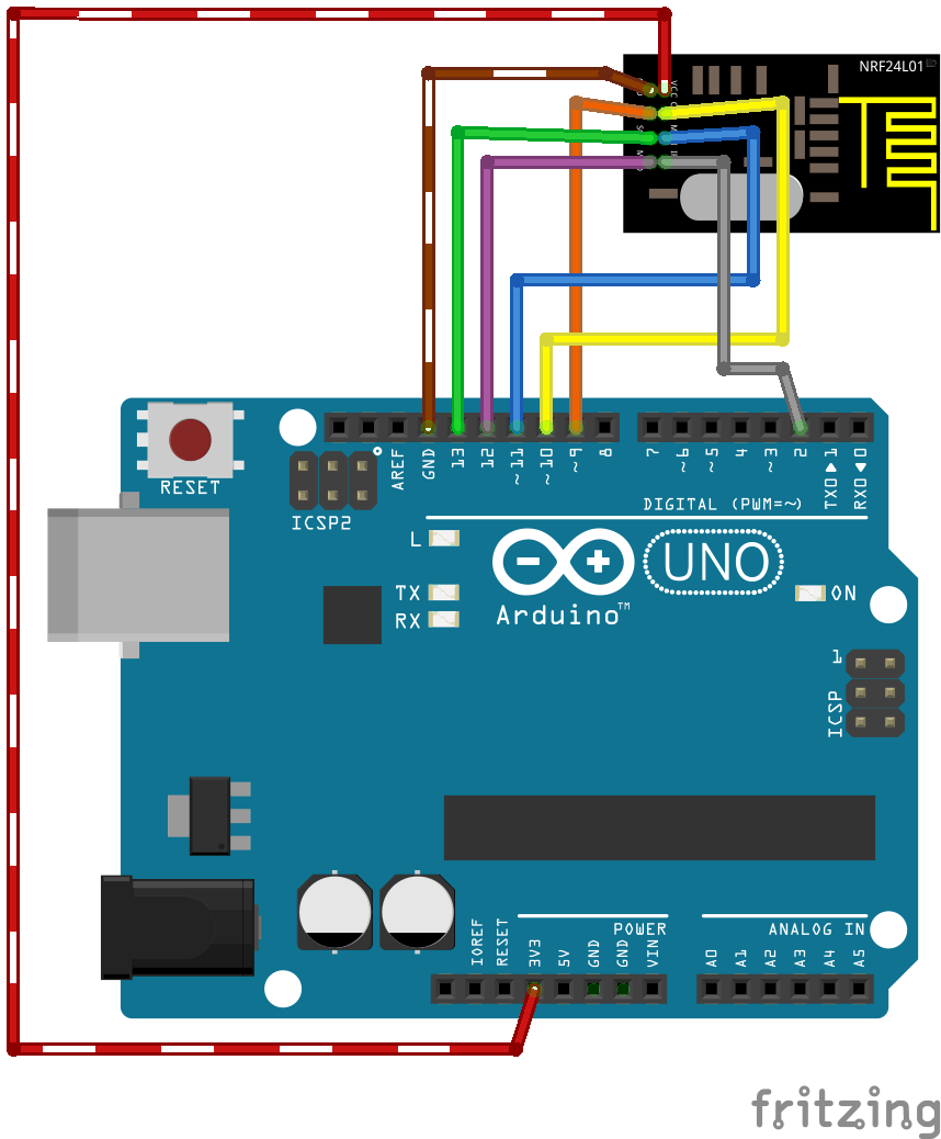
Figura 1: Conectando nRF24l01 no Arduino.
Os próximos tópicos descrevem detalhes para construção de cada tipo de nó.
Implementação Nó Gateway
Neste tópico vamos demostrar a contrução de nó gateway, que como vimos é responsável pela comunicação entre os nós finais e o controlador.
Para implementação deste nó devemos conectar o rádio nRf24l01+ no arduino e utilizarmos o código:
1 2 3 4 5 6 7 8 9 10 11 12 13 14 15 16 17 18 19 20 21 22 23 24 25 26 27 28 29 30 31 32 33 34 35 36 37 38 39 40 41 42 43 44 45 46 47 48 49 50 51 52 53 54 55 56 57 58 59 60 61 62 63 64 65 66 67 68 69 70 71 72 73 74 75 76 77 78 79 80 81 82 83 84 85 86 87 88 89 90 91 92 93 94 95 96 97 98 99 100 101 102 103 104 105 106 107 108 109 110 111 112 113 114 115 116 117 118 119 120 121 122 123 124 125 126 127 128 129 130 131 132 133 134 135 136 137 138 139 140 141 142 143 144 145 146 147 148 149 150 151 | /**
* The MySensors Arduino library handles the wireless radio link and protocol
* between your home built sensors/actuators and HA controller of choice.
* The sensors forms a self healing radio network with optional repeaters. Each
* repeater and gateway builds a routing tables in EEPROM which keeps track of the
* network topology allowing messages to be routed to nodes.
*
* Created by Henrik Ekblad <henrik.ekblad@mysensors.org>
* Copyright (C) 2013-2015 Sensnology AB
* Full contributor list: https://github.com/mysensors/Arduino/graphs/contributors
*
* Documentation: http://www.mysensors.org
* Support Forum: http://forum.mysensors.org
*
* This program is free software; you can redistribute it and/or
* modify it under the terms of the GNU General Public License
* version 2 as published by the Free Software Foundation.
*
*******************************
*
* DESCRIPTION
* The ArduinoGateway prints data received from sensors on the serial link.
* The gateway accepts input on seral which will be sent out on radio network.
*
* The GW code is designed for Arduino Nano 328p / 16MHz
*
* Wire connections (OPTIONAL):
* - Inclusion button should be connected between digital pin 3 and GND
* - RX/TX/ERR leds need to be connected between +5V (anode) and digital pin 6/5/4 with resistor 270-330R in a series
*
* LEDs (OPTIONAL):
* - To use the feature, uncomment WITH_LEDS_BLINKING in MyConfig.h
* - RX (green) - blink fast on radio message recieved. In inclusion mode will blink fast only on presentation recieved
* - TX (yellow) - blink fast on radio message transmitted. In inclusion mode will blink slowly
* - ERR (red) - fast blink on error during transmission error or recieve crc error
*
*/
#define NO_PORTB_PINCHANGES
#include <MySigningNone.h>
#include <MyTransportRFM69.h>
#include <MyTransportNRF24.h>
#include <MyHwATMega328.h>
#include <MySigningAtsha204Soft.h>
#include <MySigningAtsha204.h>
#include <SPI.h>
#include <MyParserSerial.h>
#include <MySensor.h>
#include <stdarg.h>
#include <PinChangeInt.h>
#include "GatewayUtil.h"
#define INCLUSION_MODE_TIME 1 // Number of minutes inclusion mode is enabled
#define INCLUSION_MODE_PIN 3 // Definição do pino digital para botão
#define RADIO_ERROR_LED_PIN 4 // Pino do LED de erro
#define RADIO_RX_LED_PIN 6 // Pino do LED de recebimento
#define RADIO_TX_LED_PIN 5 // Pino do LED de transmissão
// NRFRF24L01 radio driver (transmissão de baixa potência)
MyTransportNRF24 transport(RF24_CE_PIN, RF24_CS_PIN, RF24_PA_LEVEL_GW);
//MyTransportRFM69 transport;
// Definição do tipo do Hardware(Microcontrolador)
MyHwATMega328 hw;
// Definição e criação do argumento gw do tipo MySensor a partir do parâmetro WITH_LEDS_BLINKING de MyConfig.h
#ifdef WITH_LEDS_BLINKING
MySensor gw(transport, hw /*, signer*/, RADIO_RX_LED_PIN, RADIO_TX_LED_PIN, RADIO_ERROR_LED_PIN);
#else
MySensor gw(transport, hw /*, signer*/);
#endif
char inputString[MAX_RECEIVE_LENGTH] = ""; // String para manter comandos de entrada serial/ethernet
int inputPos = 0;
boolean commandComplete = false; // Se a string está completa
void parseAndSend(char *commandBuffer);
// Função para saída serial
void output(const char *fmt, ... ) {
va_list args;
va_start (args, fmt );
vsnprintf_P(serialBuffer, MAX_SEND_LENGTH, fmt, args);
va_end (args);
Serial.print(serialBuffer);
}
// Função de configuração
void setup()
{
gw.begin(incomingMessage, 0, true, 0);
setupGateway(INCLUSION_MODE_PIN, INCLUSION_MODE_TIME, output);
// Adicionando interrupção para inclusão de pino.
PCintPort::attachInterrupt(pinInclusion, startInclusionInterrupt, RISING);
// Enviar mensagem da inicialização serial.
serial(PSTR("0;0;%d;0;%d;Gateway startup complete.\n"), C_INTERNAL, I_GATEWAY_READY);
}
void loop()
{
gw.process();
checkButtonTriggeredInclusion();
checkInclusionFinished();
// Verifica se um comando serial foi emitido
if (commandComplete) {
// Comando serial tentará ser enviado ao atuador
parseAndSend(gw, inputString);
commandComplete = false;
inputPos = 0;
}
}
/*
SerialEvent ocorre sempre que for acionado o pino de
recebimento(RX). Esta rotina é executada sempre que a
função loop() for executada, portanto a resposta pode
sofrer atraso.
*/
void serialEvent() {
while (Serial.available()) {
// Pega o novo byte:
char inChar = (char)Serial.read();
// se o caractere de entrada é uma nova linha, gere uma flag (sinalizador).
// tratamento no loop principal
if (inputPos<MAX_RECEIVE_LENGTH-1 && !commandComplete) {
if (inChar == '\n') {
inputString[inputPos] = 0;
commandComplete = true;
} else {
// adicionando uma string de entrada (inputString):
inputString[inputPos] = inChar;
inputPos++;
}
} else {
// Mensagens antigas são deletadas.
inputPos = 0;
}
}
}
|
Implementação Nó Sensor
A implementação de nós sensores consiste básicamente na conexão de arduino com o rádio nRF24l01+ e a ligação do sensor desejado. A Figura 1 ilustra a ligação do arduino com o nRF24l01 a partir desse ligação deve-se adaptar para adicionar o sensor. Nos subtópicos temos a implementação de alguns sensores.
Implementação Nó Atuador
Os nós atuadores são responsáveis pela interação com o ambiente, são esses nós que realizam ações sobre os meios externos. Para implementação de um nó atuador devemos primeiro conectar o rádio no arduino, como ilustra a Figura 1 e depois devemos adicionar o atuador. Nos subtópicos temos o exemplo da implementação de alguns atuadores.
Implementação Nó Repetidor
Quando a distancia entre dois nós é maior que a distancia de alcance do rádio é necessário a implementação de um nó repetidor, esse nó utiliza apenas um arduino e um rádio, a comunicação do arduino com o rádio é feita como na Figura 1. Abaixo segue o código utilizado para o nó repetidor.
1 2 3 4 5 6 7 8 9 10 11 12 13 14 15 16 17 18 19 20 21 22 23 24 25 26 27 28 29 30 31 32 33 34 35 36 37 38 39 40 41 42 43 44 45 46 47 48 49 50 51 52 53 54 55 56 57 | /**
* The MySensors Arduino library handles the wireless radio link and protocol
* between your home built sensors/actuators and HA controller of choice.
* The sensors forms a self healing radio network with optional repeaters. Each
* repeater and gateway builds a routing tables in EEPROM which keeps track of the
* network topology allowing messages to be routed to nodes.
*
* Created by Henrik Ekblad <henrik.ekblad@mysensors.org>
* Copyright (C) 2013-2015 Sensnology AB
* Full contributor list: https://github.com/mysensors/Arduino/graphs/contributors
*
* Documentation: http://www.mysensors.org
* Support Forum: http://forum.mysensors.org
*
* This program is free software; you can redistribute it and/or
* modify it under the terms of the GNU General Public License
* version 2 as published by the Free Software Foundation.
*
*******************************
*
* REVISION HISTORY
* Version 1.0 - Henrik Ekblad
*
* DESCRIPTION
* Example sketch showing how to create a node thay repeates messages
* from nodes far from gateway back to gateway.
* It is important that nodes that has enabled repeater mode calls
* process() frequently. Repeaters should never sleep.
*/
// Enable debug prints to serial monitor
#define MY_DEBUG
// Enable and select radio type attached
#define MY_RADIO_NRF24
//#define MY_RADIO_RFM69
// Enabled repeater feature for this node
#define MY_REPEATER_FEATURE
#include <SPI.h>
#include <MySensors.h>
void setup() {
}
void presentation()
{
//Send the sensor node sketch version information to the gateway
sendSketchInfo("Repeater Node", "1.0");
}
void loop()
{
}
|
Implementação Nó Controlador
O nó controlador é responsável pela interface entre a rede contruida e a Internet, existem várias opções de controladores disponíveis, neste material utilizamos o MyController.org ou o Pimatic. Ambos podem ser utilizados em um computador pessoal ou até mesmo na raspberry ou na beaglebone.
Uma lista de controladores com suporte para a biblioteca mysensors esta disponível em https://www.mysensors.org/controller/.